With independently adjustable Q, Fo and Gain.
This project is built around the Texas Instruments UAF42 Universal Active Filter. The circuit diagram of the UAF42 is shown below.
The UAF42 IC is designed to make it possible to easily create (using the 3 op amps on the left) a second order high-pass filter with independently variable Q, resonant frequency (Fo) and Gain.
This type of filter provides a useful circuit to tailor the low-end frequency response of vented and passive radiator type subwoofer systems. For more info see, for example:
http://sound.westhost.com/qb5align.htm
Used correctly, this active filter can be used to extend the speaker passband lower in frequency and reduce the cone excursion below the resonance frequency of the system, helping to prevent driver damage and reduce distortion that would otherwise be generated. The TI UAF42 IC is designed to be used to build this type of filter and has a fourth (right most op amp in the figure above) op amp that can be used used to create an additional gain stage or output buffer, preserving overall signal polarity.
This flter, paired with a properly designed vented or passive radiator subwoofer, can maximize a driver's performace in terms of low end response and power output because the vented and passive radiator alignments typically have the highest power output constants. Additionally, passive radiator systems can be designed to have comparatively small boxes that, when compared to similar vented deisigns, eliminate the inevitable port resonances associated with the long ports that are required to achieve low tuning frequencies in small boxes.
Second Order Inverting Filter Configuration
CLICK THE IMAGE ABOVE TO ENLARGE IT
While above equations can be used to design any inverting second order high-pass filter there are some details that should be noted. The gain of this stage should be about 1 (0dB) so RG should be equal to R1. For typical bass applications, we will need to augment the on chip capacitors with a pair of well matched external caps to generate filter resonance frequencies that are in the low bass region. To adjust the frequency, we can change RF1 and RF2 together. RQ alone independently adjusts the filter Q. Since the filter circuit only uses three of the four op amps on the UAF42 IC, we can use the fourth IC (not shown here) as an inverting gain stage, connected after the inverting filter circuit shown above. This has the advantage that the overall gain can be set to any arbitrary small or large value using the fourth op-amp's gain state and the phase at the output will be the same as the input.
I have created an Excel spreadsheet that can be used to determine the component values that are needed to design this circuit to have any desired Q, Fo and Gain. You are welcome to download it and use it for your non-commercial purposes (commercial use is prohibited).
Instead of requiring each builder to computer and build a different circuit to match the driver on hand, I have designed a circuit which allows the filter parameters to be adjusted, using front panel controls, over the range of values that are typically used with a subwoofer system. This circuit has for its parameters the following ranges:
0.5 < Q < 2.0
10 Hz < Fo < 50Hz
-20dB < Gain < 10dB
The adjustability can easily be achieved using potentiometers for the gain and the Q, however this is not the case for the filter frequency and this is treated in a slightly different way.
The filter resonant frequency is controlled through a series of resistors. The value of each resistor in the series is twice the value of the previous one and each resistor can be bypassed using a toggle switch. Using 6 DPST switches and 1% tolerance resistors, the frequency can be adjusted to within about 5% of any value between 10Hz and 50Hz without effecting the filter Q. If potentiometers were used, even close tracking ones, the values of the resistors that control the frequency (RF1 and RF2) cannot be made to be sufficiently similar and the filter Q will drift as the filter frequency is changed. This setup is also easy to implement at low cost.
I also decided that, in order to achieve fine control over the filter Q, two separate potentiometers should be used to set the Q value, either within a high range (1.0 < Q < 2.0) or a low range (0.5 < Q < 1.0).
Where,
w = frequency in radians (w = 2pF, F = frequency in Hz)
A_LP = Voltage Gain (Gain in dB = 20 log A_LP)
Q = filter Q
While there are several ways to use the compenents of this IC, for this circuit the inverting filter configuration will be created using the first three op amps and the fourth op amp will be connected to it and configured as an inverting gain state so that the overall phase is preserved. The circuit for the inverting filter configuration is shown below for reference:
To date (5/26) I have assembled and tested the circuit and it works great! I had to fix some problems with hum and noise that were due to the fact that I was lazy and did not ground the input and output jacks. Also the gain pot was acting funny so I replaced it with a resistor temporarily while a replacement is on order. I hope to do some measurements of the circuit's output using my computer to check that the filter response is accurate. So far it's looking pretty good.
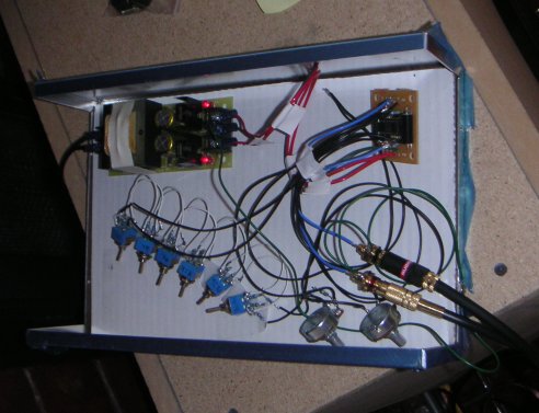
See below for a couple of pics. The circuit is still just lying in the project case, held in place with a couple of pieces of scotch tape. I am waiting for a new drill bit to arrive so that I can make the holes for the controls.
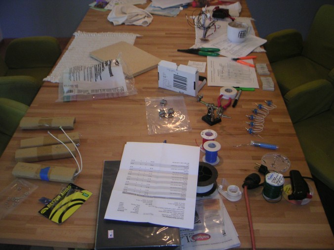
Above: A clean desk is a sign of a sick mind. No sickness here...
Below: Testing out the filter with the subwoofer. The circuit is just lying in the case since I have not drilled any of the holes for the controls. I put a piece of cardboard underneath everything to insulate everthing from the metal case.
Friday June 7th
I have discovered the ARTA test suite for electrical and loudspeaker measurements and have been finally able to put it to use for some frequency response measurements by putting only the filter circuit into a loop between output and line input. I measured the response at the extremes of both the frequency control and the filter Q control. I also measured the circuit's distortion.
Click the images to open a larger version.
Right Above:
frequency = min
Q = max
Right Below:
frequency = min
Q = min
Right Above:
frequency = max
Q = max
Right Below:
frequency = max
Q = min
Right Above:
Distortion at:
frequecncy = min
Q approximately 0.7-0.8
Right Below:
Percent Distortion


