OverView
The 4-Active Tower is a 4-way active loudspeaker system having a symmetrical driver arrangement, active crossovers, baffle-step compensation and a bass equalization network. The electronics have been designed to be re-configurable to allow the system to be tuned for a particular room environment or to allow the crossovers to be re-used in future loudspeaker projects.
Some Thoughts on Symmetric Driver Arrangements:
I did some heavy reading and thinking before coming up with the design for these loudspeakers and I want to share my thought in this section for those who are thinking of using symmetric driver layouts in their projects. I want to consider the driver arrangement typically found in "D'Appolito" or MTM type loudspeakers. There are some benefits to be gained as well as drawbacks that can really ruin an otherwise good design. Let's review some of these plusses and minuses and then see how these influenced my design.
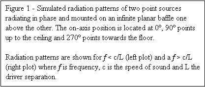
Consider the case of two identical drivers mounted in an infinite baffle, one above the other and operated in phase. The pressure waves generated by each driver combine to yield a composite wavefront that is always in phase on-axis, resulting in a gain of 3dB in the sound pressure there. Typically the drivers are connected in parallel (giving 3dB of electrical gain) for a total of 6dB of gain in sound power. Sonically speaking, one hears the "sound" of the composite wavefront originating from an "apparent center" located in between the two drivers. This gives the designer the option of locating the "apparent center" and another driver (typically the tweeter) at the same place on the baffle, in effect creating a co-incident driver. The composite wavefront shares characteristics with the cylindrical wave front developed by line arrays[1]. On the other hand, a careful consideration of the off-axis response in the vertical plane reveals some shortcomings. At "low" frequencies, f, less than or equal to c/L where c is the speed of sound and L the driver separation distance, the soundfield is smooth (Figure 1, left plot). However for higher frequencies, the sound field begins to develop "holes" in the off-axis response (see Figure 1, right plot), the number of which increases with frequency. This phenomenon is sometimes referred to as "comb filtering" or "lobing". Because there is a different pathlength between each driver and the listening position, the two wavefronts arrive out of phase. The superposition of any two waves of the same frequency having a non-zero phase difference leads to cancellation and this reduces the amplitude of the composite wave. Since not all listening is done on-axis and since off-axis nulls affect the reverberant soundfield, these considerations are important for maximizing the performance of a loudspeaker. Recall that there is no cancellation for "low" frequencies (e.g. Figure 1, left plot) because the wavefronts add together constructively (well, mostly at least) everywhere in space. Although there is no way to eliminate the off-axis frequency response nulls that are developed by this driver geometry at "high" frequencies, by restricting the operation to "low" frequencies the sonic problems can be minimized. A similar consideration is given to driver spacing in line arrays in the far-field limit where the recommended driver spacing is greater than one wavelength at the crossover point in the far field limit or one-half wavelength in the near field limit (see Reference 1). Because a real driver is not a point source and because reverberant sound masks response irregularities to some degree we can choose the less restrictive far-field rule. We can use the relationship between frequency, wavelength and the speed of sound to restate this in a slightly different form. Given the speed of sound (c, equal to 340.3 meters/sec or 1117 feet/sec at sea level) the crossover frequency (fXO, in Hertz) and the driver separation (L) we have: fXO < c/L. I have adopted this rule of thumb for driver separation in the 4Active Tower.
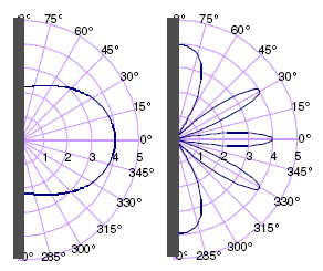
Figure 1 - Simulated radiation patterns of two point sources radiating in phase and mounted on an infinite planar baffle one above the other. The on-axis position is located at 0º, 90º points up to the ceiling and 270º points towards the floor.
Radiation patterns are shown for f < c/L (left plot) and a f > c/L (right plot) where f is frequency, c is the speed of sound and L the driver separation.
Let's now consider some real examples of the traditional woofer-tweeter-woofer driver arrangement. If we want to use a tweeter with a flange diameter of 4 inches and two 6.5 inch woofers (7-inch at the frame edge) the minimum woofer-to-woofer distance that could be achieved with these drivers mounted in a line without overlap is 11 inches. This is equal to the wavelength of a 1225 Hz tone and, following the rule-of-thumb, the crossover point must be less than or equal to this frequency. If we try to make the driver separation smaller by using 5.25 inch drivers (5.5 inch at the frame edge) and a tweeter with almost no flange (like the Morel MDT-40 which measures 2.25 inches across) we could only increase the crossover frequency to about 1750 Hz! Crossover frequencies on the order of 1kH are possible but restrict the power handling and performance of a tweeter. Additionally, because crossover frequency near 1kHz will be located where a human's hearing is most sensitive, even small sonic irregularities will color the loudspeaker's sound.
The 4Active Tower has a mid/bass-mid/dome-mid/bass driver arrangement and a crossover frequency that follows the rule-of thumb to promote smooth off-axis response. A lower crossover frequency is required because the mid/bass driver separation is increased. Luckily, a midrange driver can handle a significantly lower crossover point than a tweeter. As the crossover frequency falls below 1kHz, the driver spacing "allowed" by the rule-of-thumb increases rapidly. For example, with a crossover point of 500Hz, the center-to-center driver separation can be as large as 27 inches--plenty of room for most three driver MTM-type arrangements. In the 4-Active loudspeaker, the spacing between the two mid-bass drivers is 16 inches, which corresponds to a frequency of 850Hz. I have experimented with crossover frequencies about half (500Hz) and twice (1.5kHz) that frequency and feel that lower crossover frequencies definitely improve the soundstage and "smoothness" of the loudspeaker. With the 16-inch mid-bass driver separation I was able to locate a 19mm/0.75in dome tweeter off center between the midrange dome and the upper mid-bass driver. Since the crossover frequency to the tweeter is at 6kHz I was not concerned about its placement as long as it was as near the "acoustic center" (centered on the dome midrange).
Active Electronics
The use of active crossovers over passive ones was chosen for several reasons. First and foremost, I didn't own any equipment for measuring driver or loudspeaker frequency response, woofer impedance, etc. I felt that my best efforts to create a multi-way crossover would be a shot in the dark at best. I found that active crossover circuits were commercially available for a reasonable cost and some offered variable crossover points. Also, the advantages that are attributed to directly powering drivers with an amplifier with no passive components in between were appealing to me [2]. These include isolating the woofer and tweeter to eliminate back-EMF into the tweeter, increased damping factor seen by the driver, eliminating the need to employ resonance damping or Zobel networks and being able to match driver levels via amplifier gain rather than having to resort to matching driver outputs to the least efficient driver in the system. The added flexibility of being able to change crossover points easily or switch drivers without remaking the crossover network was very appealing to me as a DIY enthusiast. I decided to buy several pre-assembled crossover modules (available from Marchand Electronics, model XM-1) and combine them into a multi-way crossover system.
In addition to the crossovers, there are boost and compensation circuits in the active electronics. I have always been interested in low-frequency equalization and assisted low-frequency loudspeaker alignments. I use a version of the Linkwitz Transform dual-integrator circuit [3] [4] that augments sealed alignments to beat Hoffman's Iron Law [5] [6] and is similar to the INFRA dual-integrator circuit used in the popular subwoofers from Bag End http://www.bagend.com/ that are known for their low bass and small cabinets. The circuit used in the 4Active Tower is known as the "Bassis" bass correction equalizer (Marchand Electronics http://marchandelec.com/ model WM-8). The Bassis uses a biquadratic filter circuit in which one quadratic filter is set up to "cancel out" the transfer function of the existing second-order closed-box system and the other is used to create a "new" second-order transfer function. The Bassis circuit allows the user to adjust the new resonance frequency and Q to fine tune the "feel" or "weight" of the bass as well as to extend the low frequency response. Additional amplifier power, often significantly more than what is needed for passband level matching, is required at frequencies below the system resonance frequency, where a12dB/octave boost is supplied to the speaker to boost the response. Because high-power solid-state amplifiers sufficient for reproducing frequencies between 10Hz and 100Hz are commonplace and relatively inexpensive, this approach to low bass is very practical. Also, since closed-box alignments are the most forgiving and easily constructed it lends itself well to the DIY enthusiast. When choosing drivers for this application, one must always keep in mind that low-bass sound pressure is limited by cone displacement in closed box systems. Drivers with a high volume displacement and that are able to dissipate large amounts of input power are best suited for this application. For instance, in a previous subwoofer application of mine, the Bassis circuits were used with 18 inch professional drivers, each in 3 cubic foot enclosures, for great effect. In the 4Active system, the Bassis circuit is used in conjunction with multiple 8 inch drivers having a total displacement of approximately 3.7 litres (for both loudspeakers) to provide a sufficient amount of volume displacement.
The most recent addition to the electronics suite has been a baffle diffraction compensation circuit. Based on the design of Alex Megann [7], it employs a shelving circuit to reduce high frequencies above the "baffle-step". The baffle step [8] [9] [10] occurs because the power of the sound emitted by the drivers depends on the "space" into which the sound is propagating and is related to the reason that a horn loaded driver has a much higher sensitivity than the same driver mounted on a planar baffle. This "baffle step" occurs when the distance to the edges of a baffle from the surface of a driver is on the order of the wavelength of radiation (sound) that the driver is producing. Typically there is a broad transition from about 100Hz to 1kHz (depending on the baffle width) over which the speaker efficiency increases by about 3-6dB. This occurs because the long wavelengths of "bass" frequencies "see" past the edge of the cabinet into the open space of the room around the loudspeaker. Frequencies above 1kHz have wavelengths that are typically equal to or smaller than the width of the front of most loudspeaker cabinets (the "baffle") and so sounds made up of higher frequencies do not "see" past the cabinet. Because of this, high frequencies only radiate into "half-space" and so have twice the sound power. The baffle step compensation circuit gradually boosts the signal with decreasing frequency over the frequency range spanned by the baffle step. If the response of the circuit is adjusted to "mirror" the loudspeakers frequency response, the frequency response of the loudspeaker system can be equalized to achieve a "flat" response that results in more natural sound reproduction. The compensation circuit has been implemented in this system using two multi-position switches. One switch selects from several center frequencies that would be typical of loudspeakers having baffle widths from 12cm to 35cm. The other switch selects the amount of boost applied at lower frequencies in steps of 1dB. By selecting the appropriate center frequency and boost the response of most loudspeakers can be equalized.
Flexibility of the Active Circuits Electronics
It is by design that the electronic circuits are adjustable. Each stage (or all stages) of the crossover circuit can be bypassed so that an all-pass, 2-way, 3-way or 4-way crossover system can be realized. The overall input level and each output level can be attenuated to adjust amplifier gain to driver efficiency. The baffle step compensation circuit can be adjusted for use with a wide variety of baffle widths and loudspeaker responses or switched out of the circuit. While passive crossovers often use baffle-step compensation via staggered crossover points or shelving networks, the nature of passive networks means that the topology is fixed, e.g. you assume some level of room loading and design for that. If you move the speakers out farther into the room or closer to a wall or corner, room loading changes will influence the frequency response in the mid-bass area. For this reason, many loudspeaker reviewers take great pains to find the "optimum listening position" and often note this in their text. With the adjustable baffle-step compensation incorporated into the active crossover for the 4Active Tower, the center frequency and overall boost of the network can be adjusted to suit different listening environments. Similarly, the bass response shaping provided by the Bassis circuit can easily be tailored for new environments and different drivers or bypassed if the boost is not desired or needed. Since each part of the active electronics is adjustable, there is considerable freedom to adapt the response to new listening environments. Similarly, the electronics can easily be re-used in another active loudspeaker system that employs a completely different design or driver layout.
Musings on the Design and System Set-up:
Central to the 4Active Tower system was the idea of creating a large, visually impressive floor-standing "tower" speaker that would allow realistic playback levels and dynamic response in both large and small rooms. By locating the drivers that produce all but the lowest notes in the center of the baffle using a symmetric driver arrangement and employing the DSRT principle to choose the crossover points I hoped to have a relatively small, compact source that would result in good imaging. I chose multiple 8-inch drivers for the lowest frequencies in order to limit baffle width and, after some minor design revisions motivated by my cabinetmaker, arrived at the current design. Using electronic crossovers with steep (24dB/octave) slopes permits operation near resonance (e.g. tweeter) or rolloff (e.g. mid-dome). For instance, the 51AT dome can be operated down to 500 Hz despite having a resonance frequency of 480 Hz and the crossover frequency to the D21/2 tweeter can be located as high as 6kHz to 8kHz. The implementation of the 4th-order crossover insures that the drivers are always in phase throughout the crossover region. By choosing drivers with good off-axis response, taking into account displacement and thermal limited power and avoiding driver response irregularities a system that is well-integrated and capable of high output can be achieved.
A four-way loudspeaker system provide several advantages. Each driver reproduces a smaller portion of the frequency spectrum as compared to 3-way or 2-way systems. This makes the task of matching driver response and crossover points easier for the DIY loudspeaker designer who is forced to use off-the-shelf components. Drivers that are not required to reproduce widely differing frequencies will demonstrate reduced Doppler distortion [11] [12]. When multiple identical drivers reproduce the same portion of the frequency spectrum, the cone excursion of each driver is reduced for the same sound pressure (as a single driver) and this helps to reduce the amount of harmonic and IM distortion [13] [14]. All of these advantages are inherent in the design of the 4Active Tower.
I feel that the speaker system presents a well balanced sound, with great impact and dynamic range. The only shortcoming might be that the soundstage is not extremely 3-dimensional however this may due to the influence of my listening environment or the equipment in my reproduction chain. I hope to meet some other DIYers in the area and swap equipment in and out to probe for some of the weaknesses of my current system: a Rotel RB-956AX 6-channel amp (40WPC), a Carver m1.0t stereo amp (200WPC) and an Adcom GFP-555 preamp. My source is a consumer-grade Sony CD/DVD player. I have to admit that I am also not an aficionado of "audiophile grade" accessories such as line conditioners, power cords, interconnects and speaker cables since I feel that many of these products are sucessful more because of marketing than real science.
In terms of practical matters, I have several reservations about the current 4Active Tower system:
(1) The cabinets are difficult to move. I think that they weigh about 80 lbs each and are difficult to manage because of their size. The veneer is peeling off. I will probably deconstruct these monsters and try to remake the system in a sat-sub mode.
(2) Despite having eight woofers and a couple of liters of total displacement the deep bass can't keep up with the output from the rest of the system. I think that this is because the woofers are located out in the room with the speakers and therefore do not couple to the room well. Even more displacement is needed to reproduce 20-40Hz loudly without pushing the excursion limits of the drivers. A separate subwoofer can be located independently from the satellites, wherever the bass reproduction is best and multiple subwoofers can even out room modes that play havoc with the bass response below 100Hz.
(3) With two Seas M14RCY drivers in parallel, the impedance minimum falls to about 2.9 ohms in that amplification channel. My Rotel amp really doesn't like this and some audible nasties can be heard even at moderate levels. I think that the cure for this will be to put a power resistor in series to increase the resistance to at least 6 ohms, a much easier load to drive. Simulations with UniBox show that I could add up to about 4ohms without losing too much sensitivity. This increases the apparent Q but this isn't a problem because the system Q was already overdamped. I am planning on trying this fix in the next couple of weeks.
(4) Lastly, with extended critical listening I sense that the LPG dome occasionally "beams" or "honks" although this isn't noticeably in casual listening. I plan to try a non-metallic cone driver in place of the aluminum dome when I rebuild the system. This decision was made easier for me when one of the domes was slightly damaged during a recent long distance move.
I thought I would mention that balancing the levels in the system is a time consuming task, especially when accomplished by ear with music. If I had a system to measure the frequency response of the loudspeaker I would have a much less subjective way to do this however to date I have not had the opportunity to use one. I'm hoping to put together a budget measuring system based on Speaker Workshop http://www.audua.com/ in the near future to help with setup and design. With four stereo channels of amplification, the Bassis circuit boost and baffle-step compensation to adjust, there are many degrees of freedom. Each tweak slightly affects the overall tonal balance and one tweak leads to another, then another and so on--an iterative process can easily last several hours. Luckily, with the active electronics, all the adjustments can be made quickly while listening to music!

Information on the Drivers Used in the 4-Active Loudspeaker:
Tweeters: Dynaudio D21/2, 3/4-inch treated fabric dome
Mid-dome: LPG 51AT, 2-inch aluminum dome
Mid-bass: Seas MP14RCY, 5-inch polypropylene cone
Woofers: Seas L21RNX/P, 8-inch aluminum cone with phase plug
References and Further Reading:

